2021年9月2日

esp32 arduino ide 編譯error

參考文章:https://youyouyou.pixnet.net/blog/post/119410732


首先在進入「檔案>偏好設定」,在「額外的開發板管理員網址」裡面加上以下的網址:

https://dl.espressif.com/dl/package_esp32_index.json 

接著再到選單「工具>開發板>開發板管理員」,尋找「es32」,就能找到我們要的選項,安裝它就可以了!

再來就找得到NodeMCU-32S

 arduino ide 編譯時出現 error

.arduino15/packages/esp32/tools/esptool_py/2.6.1/esptool.py", line 37, in <module>
      import serial
      ImportError: No module named serial
解決方式:
sudo apt install python-is-python3
pip3 install pyserial
 
再編譯,錯誤訊息就沒了。
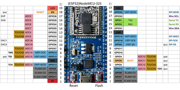


另一款腳位圖


  • GPIO 34,35,36,39:Input only(不能作為輸出腳位)
  • GPIO 0,6,7,8,9,10,11:系統用,勿使用(淺灰色標示)
  • GPIO 18:重開機

還有一些個人遇到的問題(不清楚原因,但會搞死你)

  • 1. DHT11不可以用GPIO 5、26
  • 2. GPIO 12, 2燒錄時不可接任何裝置,請空接,燒錄完成後,再接回,否則會上傳失敗。
  • 3.WiFi啟動後,2,4,12,13,14,15,25,26,27僅能數位讀取,不可類比


有一款esp32腳位標在背面,插入擴充板後完全看不到。


oled qrcode

可以參考這篇

https://techtutorialsx.com/2017/12/16/esp32-arduino-ssd1306-oled-drawing-a-qr-code/


2021年8月20日

arduino uno 當bootloader

參考文章:

 http://programmermagazine.github.io/201405/htm/article1.html


兩張板子的 pin 11 ~ pin 13 兩兩對接,pin 11 接 pin 11,pin 12 接 pin 12,pin 13 接 pin 13。 兩張板子的 5V 與 Gnd 也是兩兩對接,5V 接 5V,Gnd 接 Gnd。 最後,ArduinoISP 的 pin 10 接到 Target board 的 Reset pin。

2021年8月19日

picoboard變uno

 記錄一下,免得又忘了。

motoduino的picoboard 是用ATmega328晶片去做的。用志文老師的方法,可以把picoboard改韌體,變成一片uno。


找一塊uno,燒錄範例arduinoisp,把燒錄器改成arduino as ISP,再選擇工具/bootloader。燒錄bootloader前要把腳位接好,可以參考之前的文章。

https://wdpsestea.blogspot.com/2019/11/picoboarduno.html

燒好後,各感應器的腳位為:

1.J4-A1(D15),

2J3-A2(D16),

3J2-A4(D18),

4按鈕D2,

5.J1-A5(D19),

6光敏A6(D20),

7.聲音micA3(D17),

8滑桿(A0)]

但我使用digitalRead(2)一直讀不出按鈕的值。看了好多文章,都無解。

最後終於查到這個D2要額外啟動才行

在void setup()要加上

    DDRD  &= ~( 1 << PD2 );     // Clear the PD2 pin and set PD2 (PCINT0 pin) now as input
    PORTD |= (1 << PD2);        // Set PIN PD2 as INPUT with pull-up enabled

    EICRA |= (1 << ISC00);      // set INT0 to trigger on ANY logic change
    EIMSK |= (1 << INT0);       // Turns on INT0

按鈕未按時,D2的值是1,按下去D2的值是0


2021年8月10日

自走車之於教學

 1.展示自走車並觀察之

2.提問自走車為何會動


3.馬達作動原理?


4.把3V的直流電正反試接,馬達有何反應?


 5.馬達轉速如何調整?


6.規納出直流馬達作動的二要素:正反轉和轉速


7.數位與類比,正反轉是?轉速是?


8.使用microbit找出數位和類比腳位,做出使馬達作動


9.自走之有二個馬達,前進後退左右轉,這二個馬達是如何相互配合做動?(凱斯車子馬達腳位被設定了無法改變,p1  p2為馬力pwm輸出,p8 p12為正反轉數位輸出)


2021年8月7日

web serial api記事

不錯的文章 

https://wicg.github.io/serial/

https://github.com/svendahlstrand/web-serial-api

https://github.com/rafaelaroca/web-serial-terminal

 https://ithelp.ithome.com.tw/articles/10161189

 連線

port = await navigator.serial.requestPort({});
await port.open({ baudRate: 9600 });

寫入資料

const encoder = new TextEncoder();
const writer = port.writable.getWriter();
await writer.write(encoder.encode(value));
writer.releaseLock();

讀出資料

reader = port.readable.getReader();
let value = await reader.read();
let uint8array = new TextEncoder().encode("¢");
let string = new TextDecoder().decode(value.value);
string = string.split('\r\n');
analog_inputs[pin] = string[0];
//console.log('analog_inputs[pin]=',analog_inputs[pin]);
reader.releaseLock();


scratch-gui無法用async 需要npm  install  babel-polyfill

//async await estea
require('babel-polyfill');


arduino code

void setup() {
  Serial.begin(115200);
  pinMode(13, OUTPUT);
}
void loop() {
  int cmd = Serial.parseInt();
  if(cmd == 1){
    digitalWrite(13, HIGH);   
  }else if (cmd == -1){
    digitalWrite(13, LOW);   
  }
  Serial.println(analogRead(A0));
}

2021年7月23日

多重開機隨身碟ventoy

 試了一下還不錯用,安裝也相當簡單。只要安裝好後把iso放入即可使用,支援grub和uefi。

下載ventoy:https://www.ventoy.net/en/download.html

 我使用linux下載.gz檔,並解壓縮

進入解壓縮目錄,看一下README,開啟終端機執行

sudo sh Ventoy2Disk.sh  -i /dev/sdX

sdX為隨身碟代號

再來把iso複製進入隨身碟就完工了。


2021年7月1日

在OSEP中使用NodeMCU ESP8266

在OSEP中使用NodeMCU ESP8266

0.認識NodeMCU

D0==>16
D1==>05
D2==>04
D3==>00
D4==>02
D5==>14
D6==>12
D7==>13
D8==>15
D9==>03
D10==>01

GPIO是什麼:https://zh.wikipedia.org/wiki/GPIO

類比腳位是A0

esp8266介紹:https://pcbdesign88.wordpress.com/2018/04/11/nodemcu%E9%96%8B%E7%99%BC%E6%9D%BFesp8266-wifi%E6%A8%A1%E7%B5%84%E4%BB%8B%E7%B4%B9/

 1.安裝osep

安裝osep 

2.arduino ide燒錄韌體(含wifi ssid和密碼)

 arduino ide燒錄設定:https://wdpsestea.blogspot.com/2021/06/arduino-ide-nodemcu.html

注意:NodeMCU ESP8266只支援wifi 2.4G無線連接,請不要設定5G AP的連線

3.執行osep s3-extend-tool連上s3e


4.執行線上或是離線版的osep_scrathc3,開啟擴充套件esp8266

osep線上版:https://ys-fang.github.io/OSEP/app/


5.數位角位輸出亮led燈


使用D2(GPIO12)來亮啟LED燈。


6.讀取數位角位信號


7.做類比數位輸出pwm-呼吸燈

8.讀取類比腳位信號

NodeMCU只有一個類比腳位A0


9.接伺服馬達

伺服馬達是高用電的設備,現在常見的伺服馬達,建議要接5V的外接電源,電流量要300MA,單一NodeMCU的電量不足以支持伺服馬達。圖使用腳位為D2(GPIO4)

10.超音波測距HC-SR04

圖使Echo用D1(GPIO5)和Trig用D2(GPIO4)

其他:

 fritzing:

https://fritzing.org/download/

 https://github.com/fritzing

https://www.npackd.org/p/fritzing/0.9.6


教學播放清單:

https://youtube.com/playlist?list=PL52qbzg6rwU65672-2hjKSuNagPTB_0cX

osep_scratch3線上版:https://sites.google.com/view/osep-scratch3/%E7%B7%9A%E4%B8%8A%E8%B3%87%E6%BA%90