顯示具有 bpi-bit 標籤的文章。 顯示所有文章

2020年1月17日

bpi-bit離線版製作記錄

參考網址:https://github.com/junhuanchen/scratch3-eim-mpfshell

建立scratch3目錄,並進入目錄中
mkdir scratch3
cd scratch3
sudo npm  add uglifyjs-webpack-plugin
sudo npm install -g webpack
sudo npm install -g webpack-dev-server

下載github中的scratch-gui
git clone https://github.com/LLK/scratch-gui
cd scratch-gui
npm install
使用瀏覽器輸入http://0.0.0.0:8601/可以看到scratch3官方編輯器了

bpi-bit擴充積木,需要兩個github專案,如下:
https://github.com/junhuanchen/scratch3-eim-mpfshell
https://github.com/CodeLabClub/scratch3_eim

回到scratch3目錄下
cd scratch3
git clone https://github.com/junhuanchen/scratch3-eim-mpfshell.git
git clone https://github.com/CodeLabClub/scratch3_eim.git
把複製專案vm到目錄中
cp -r scratch3_eim scratch-gui/node_modules/scratch-vm/src/extensions/
cp -r scratch3-eim-mpfshell/scratch3_mpfshell scratch-gui/node_modules/scratch-vm/src/extensions/
 cp -r scratch3-eim-mpfshell/scratch3_bpibit scratch-gui/node_modules/scratch-vm/src/extensions/
編輯index.jsx
vim scratch-gui/src/lib/libraries/extensions/index.jsx
在import 下一行,加入下列內容
//bpibit
import mpfshellImage from './mpfshell/mpfshell.png';
import WebduinoImage from './bpibit/webduino.png';

在export default [中最後面加入(注意有個",")
    ,
    {
        name: 'Mpfshell',
        extensionId: 'mpfshell',
        collaborator: 'JunhuanChen',
        iconURL: mpfshellImage,
        description: (
            <FormattedMessage
                defaultMessage="Mpfshell for Scratch3"
                description="Use mpfshell control micropython."
                id="gui.extension.Mpfshell.description"
            />
        ),
        featured: true
    },
    {
        name: 'bpi:bit',
        extensionId: 'bpibit',
        collaborator: 'Bananapi',
        iconURL: WebduinoImage,
        description: (
            <FormattedMessage
                defaultMessage="bpi:bit for scratch3"
                description="bpibit"
                id="gui.extension.bpibit.description"
            />
        ),
        featured: true
    }

編輯extension-manager.js
vim scratch-gui-ok/node_modules/scratch-vm/src/extension-support/extension-manager.js
註解掉 //gdxfor: () => require('../extensions/scratch3_gdx_for'),

加入下列內容
,
//mpfshell: Scratch3MpfshellBlocks,
    eim: () => require('../extensions/scratch3_eim'),
    mpfshell: () => require('../extensions/scratch3_mpfshell'),
    bpibit: () => require('../extensions/scratch3_bpibit'),


把圖檔拷貝進入目錄(好像少了mpfshell.png,自己找一張吧)
mkdir scratch-gui/src/lib/libraries/extensions/bpibit
mkdir scratch-gui/src/lib/libraries/extensions/mpfshell
 cp scratch3-eim-mpfshell/webduino.png scratch-gui/src/lib/libraries/extensions/bpibit/
cp scratch3-eim-mpfshell/mpfshell.png scratch-gui/src/lib/libraries/extensions/mpfshell/
重新執行npm start
 就可以看到bpi-bit的擴充積木了,

至於連線程式請參考https://adapter.codelab.club/user_guide/install/
 說明,燒入韌體和執行連線程式.

中文化

vim scratch-gui/node_modules/scratch-l10n/locales/editor-msgs.js
 加入下列內容
 "bpibit.isconnected": "是否連線",
    "bpibit.connect": "連線",
    "bpibit.close": "關閉",

vim scratch-gui/node_modules/scratch-vm/src/extensions/scratch3_bpibit/index.js


在bpibit部分中在
blocks: [
                {
                    opcode: 'isconnected',
                    blockType: BlockType.REPORTER,
下加入下列內容
text: formatMessage({
                        id: 'bpibit.isconnected',
                    }),

再到網頁中就可以看到中文化完整的內容


2018年11月22日

bpi-bit mycropython記事


安裝picocom

sudo apt-get install picocom
sudo pip install adafruit-ampy --upgrade

確認 esptool安裝完成

sudo apt-get install esptool
sudo pip3 install esptool

燒錄硬體

下載網址:https://github.com/BPI-STEAM/BPI-BIT-MicroPython/releases
 下載:firmware.bin、AutoErase.py、AutoFlash.py三個檔案。
開啟終端機,輸入:
python3 AutoErase.py
python3 AutoFlash.py

連線到bpi-bit

picocom /dev/ttyUSB0 -b 115200

關閉wifi AP

wifi.close()

執行.py檔案

ampy --port /dev/ttyUSB0 run led.py

Ctrl+A在空行上,輸入原始REPL模式
Ctrl+B在空行上,進入正常的REPL模式
Ctrl+C中斷程序
Ctrl+D軟體重啟
Ctrl+E進入複製貼上程式碼模式,做完貼上使用Ctrl+D執行貼上程式碿
按Ctrl+A 再按Ctrl+Q離開終端機
如果要燒錄進去,則把xx.py程式,改成main.py
sudo ampy --port /dev/ttyUSB0 put main.py
刪除板子上的文件
ampy --port /dev/ttyUSB0 rm led.py
下載檔案到電腦中
ampy -p /dev/ttyUSB0 get xx.py
列出文件
ampy -p /dev/ttyUSB0 ls
清除micropyton重新燒入 
sudo esptool.py --port /dev/ttyUSB0 erase_flash
sudo esptool.py --port /dev/ttyUSB0 --baud 460800 write_flash --flash_size=detect 0 esp8266-20180511-v1.9.4.bin

點亮GPIO 18 LED燈

載入machine裡的Pin類別
from machine import Pin
載入時間物件
import time
設定GPIO 18為輸出,GPIO18在bpi-bit正面wf32晶片旁bpi:bit的正方方LED燈
LED = Pin(18, Pin.OUT)
亮燈
LED.value(1)
熄燈
LED.value(0)
 

呼吸燈作法

import machine,time
LED = machine.PWM(machine.Pin(18), freq=1000)
tick = 0 # counter variable
while True:
    if tick < 40:
        # self.tick % 20 gives a number 0 to 19
        # subtracting 9 makes it -9 to 10
        # abs maps it 9 to 0 to 10
        # subtracting from 10 maps it 1 to 10 to 0
        # multiplying by 25 scales it 25 to 250 to 0
        LED.duty((10 - (abs((tick % 20) - 9))) * 25)
        tick = (tick + 1) % 40
        time.sleep(0.1)
注意程式碼階層,python以階層決定程式碼位置。
可以貼在文件編輯器中存成led_pwm.py檔,放終下列執行指令
 ampy --port /dev/ttyUSB0 run led_pwm.py

2018年11月10日

bpi-bit buzzer music

參考midi網址:https://en.m.wikipedia.org/wiki/Scientific_pitch_notation#Table_of_note_frequencies


 #define Buzzer 25   //GPIO 25

// 0 NULL 0.0001
// 5    LG 196.00
// 5.5  #LG 207.65
// 6    LA 220.00
// 6.5  #LA 233.08
// 7    LB 246.94
// 11    C 261.63
// 11.5 #C 277.18
// 12    D 293.66
// 12.5 #D 311.13
// 13    E 329.63
// 14    F 349.23
// 14.5 #F 369.99
// 15    G 392.00
// 15.5  #G 415.30
// 21    A 440.00
// 21.5  #A 466.16
// 22    B 493.88

#define TIME 250       // 1拍時間
#define LEDC_CHANNEL 0    
#define LEDC_TIMER_BIT 13
#define LEDC_BASE_FREQ 5000
double music_star[] = {11,11,15,15,16,16,15,0,14,14,13,13,12,12,11,0,15,15,14,14,13,13,12,0,15,15,14,14,13,13,12,0,11,11,15,15,16,16,15,0,14,14,13,13,12,12,11,0 };
double music_happy[] = {5,5,6,5,11,7,0,5,5,6,5,12,11,0,5,5,15,13,11,7,6,0,0,0,14,13,12,11,0 };
double music_ode[] = {7,7,11,12,12,11,7,6,5,5,6,7,0,6,6,0,7,7,11,12,12,11,7,6,5,5,6,7,6,0,5,5,0};

void setup(){
  ledcSetup(LEDC_CHANNEL, LEDC_BASE_FREQ, LEDC_TIMER_BIT);
  ledcAttachPin(Buzzer, LEDC_CHANNEL);
}

double to_num(double m_n){
double r_n = 0.00;
if (m_n ==5){
  r_n = 196.00;
}else if( m_n ==5.5){
  r_n = 207.65;
}else if ( m_n == 6){
  r_n = 220.00;
}else if ( m_n == 6.5){
  r_n = 233.08;
}else if ( m_n == 7){
  r_n = 246.94;
}else if ( m_n == 11){
  r_n = 261.63;
}else if ( m_n == 11.5){
  r_n = 277.18;
}else if ( m_n == 12){
  r_n = 293.66;
}else if( m_n == 12.5){
  r_n = 311.13;
}else if( m_n == 13){
  r_n = 329.63;
}else if( m_n == 14){
  r_n = 349.23;
}else if( m_n == 14.5){
  r_n = 369.99;
}else if( m_n == 15){
  r_n = 392.00;
}else if( m_n ==15.5){
  r_n = 415.30;
}else if( m_n == 16){
  r_n = 440.00;
}else if( m_n ==16.5){
  r_n = 466.16;
}else if( m_n == 17){
  r_n =493.88;
}else if( m_n ==21){
  r_n =523.25;
}
   return r_n ;
}


void loop(){
  for (int i=0;i<sizeof(music_happy)/8;i++)
  {
  
    if (to_num(music_happy[i]) == 0){
          delay(TIME);
      }else{
        ledcWriteTone(LEDC_CHANNEL, to_num(music_happy[i]));
        delay(TIME);
        }
    }
  
  ledcWriteTone(LEDC_CHANNEL, 0);
  delay(1000);
}

2018年11月1日

micropython 連bpi-bit

apt-get install picocom
 pip3 install esptool

github
 https://github.com/BPI-STEAM/BPI-BIT-MicroPython


燒入micropython韌體
檔案下載
https://github.com/BPI-STEAM/BPI-BIT-MicroPython/releases/tag/beta 

python3  AutoErase.py
python3 AutoFlash.py

連上bpi-bit
picocom /dev/ttyUSB0 -b 115200

關掉wifi指令
wifi.close();

2018年10月10日

bpi-bit arduino 數位類比pwm

使用bpi-bit 在arduino ide上使用數位角位輸出-P2

參考網址:https://www.cnblogs.com/lulipro/p/8046248.html
void setup() {
  // put your setup code here, to run once:
  pinMode(P2, OUTPUT);
}

void loop() {
  // put your main code here, to run repeatedly:
  digitalWrite(P2, HIGH);
  delay(500);
  digitalWrite(P2, LOW);
  delay(500);
}

要使用pwm來做呼吸燈


int freq = 5000;
int ledChannel = 0;
int resolution = 8;

void setup() {
   ledcSetup(ledChannel, freq, resolution);
  ledcAttachPin(P1, ledChannel);
 }
void loop()
{
  for (int dutyCycle = 0; dutyCycle <= 255; dutyCycle++) {
    ledcWrite(ledChannel, dutyCycle);
    delay(7);
  }

  for (int dutyCycle = 255; dutyCycle >= 0; dutyCycle--) {
    ledcWrite(ledChannel, dutyCycle);
    delay(7);
  }

}


P1類比輸入 

把類比感應器接在P1,使用serial monitor秀出。

void setup() {
  // put your setup code here, to run once:
    Serial.begin(115200); //Serial Port Config 115200-8-N-1
    pinMode(P1, INPUT_PULLUP);
}

void loop() {
  // put your main code here, to run repeatedly:
      Serial.println();
      Serial.println(analogRead(P1));
      delay(500);;

}

P1數位輸入

把數位感應器接在P1(按鈕),使用serial monitor秀出
void setup() {
  // put your setup code here, to run once:
    Serial.begin(115200); //Serial Port Config 115200-8-N-1
    pinMode(P1, INPUT);//Botton B Pin Mode :Digital Input
}

void loop() {
  // put your main code here, to run repeatedly:
  if (digitalRead(P1) == LOW)
    {
      delay(100);
   if (digitalRead(P1) == LOW)
    {
      Serial.println();
      Serial.println(LOW);
    }else{
      Serial.println();
      Serial.println(HIGH);
    }
   }
 
}

2018年10月8日

bpi-bit LED 數位亮燈

arduino ide 實作led亮燈

開一個arduino新檔,板子選擇bpi-bit(板子設定方法請參考https://wdpsestea.blogspot.com/2018/10/bpi-bit-arduino-ide.html ,ubuntu使用者參考https://wdpsestea.blogspot.com/2018/09/bpi-bit-arduino-ide.html ) 選擇連擁port(win下是comX,linux下是ttyUSBX),燒錄速度建議降低些。


void setup() {
  // put your setup code here, to run once:

}
前include下列檔案
我們有25個LED和使用PixelPin 4來溝通。

#include <Arduino.h>
#include <NeoPixelBus.h>
#include "WiFi.h"
//WS2812 config
const uint16_t PixelCount = 25;
const uint8_t PixelPin = 4;
NeoPixelBus<NeoGrbFeature, Neo800KbpsMethod> strip(PixelCount, PixelPin);


#define colorSaturation 32
//定義WS2812 腳位 2
#define ledPower 2
//定義顏色
RgbColor red(colorSaturation, 0, 0);
RgbColor green(0, colorSaturation, 0);
RgbColor blue(0, 0, colorSaturation);
RgbColor white(colorSaturation);
RgbColor black(0);
HslColor hslRed(red);
HslColor hslGreen(green);
HslColor hslBlue(blue);
HslColor hslWhite(white);
HslColor hslBlack(black);


void setup() {
  // put your setup code here, to run once:

}
中加入
  Serial.begin(115200); //Serial Port Config 115200-8-N-1
  while (!Serial); // wait for serial attach

  Serial.println();
  Serial.println("Initializing...");
  Serial.flush();

  // this resets all the neopixels to an off state
  strip.Begin();
  strip.Show();

  pinMode(ledPower,OUTPUT);
  digitalWrite(ledPower, HIGH); //It's very important for the v1.2, if you use the v1.4 ,you can delete it


在void loop() {
  // put your main code here, to run repeatedly:
           
}
中插入下列
            strip.SetPixelColor(0, red);
            strip.Show();
            delay(100);
            strip.SetPixelColor(0, black);
            strip.Show();
            delay(100);
亮燈,strip.SetPixelColor(0, red);0是第幾個燈按照下圖排列,顏色則按RgbColor定義的內容

 要熄滅則用黑色
strip.SetPixelColor(0, black);
間隔時間使用delay(微秒),1秒=1000微秒。
 delay(1000);


2018年10月4日

bpi-bit 使用arduino ide編輯

arduino ide 不認識bpi-bit這板子,arduino ide要如何設定?
參考文章:https://github.com/BPI-STEAM/BPI-BIT-Arduino-IDE/wiki/windows

1.下載arduino ide  個人使用zip檔案:https://www.arduino.cc/en/Main/Software
 選擇適合自己做業系統的zip,下載後解壓縮。

2.bpi-bit是使用esp32晶片,所以要找到arduino esp32的硬體程式,在https://github.com/espressif/arduino-esp32
下載後解壓縮。改目錄名稱為esp32,放到arduino 1.8.7的hardware目錄下建一個espressif目錄下

感謝Yufong提供,在偏好設定中加入https://dl.espressif.com/dl/package_esp32_index.json,就有bpi-bit的板子可以選。


執行esp32/tools/get.exe

執行arduino 1.8.7,這時就有bpi-bit的板子可以選擇了。

加入全彩LED陣列模組
參考文章:http://wiki.banana-pi.org/Lighting_the_RGB_LED
下載程式庫 Librarys:[NeoPixel_Bus] from Makuna:https://github.com/Makuna/NeoPixelBus
 下載完解壓縮,放到arduino ide的libraries目錄中


啟動arduino ide,點選[工具/管理程式庫],在搜尋框中輸入:neopixe,安裝neopixebus by makuna程式庫。

開啟範例:

 找到這兩行(約第16 17行)
const uint16_t PixelCount = 4; // this example assumes 4 pixels, making it smaller will cause a failure
const uint8_t PixelPin = 2;  // make sure to set this to the correct pin, ignored for Esp8266
改成
const uint16_t PixelCount = 25; // this example assumes 4 pixels, making it smaller will cause a failure
const uint8_t PixelPin = 4;  // make sure to set this to the correct pin, ignored for Esp8266

 (約67行)找到setup()在{下一行加入
#define LED_POWER      2
 pinMode(LED_POWER, OUTPUT);
 digitalWrite(LED_POWER, HIGH);
 
確認你的bpi-bit在哪個com port,就可以燒錄了。燒錄完會看到LED燈亮起。
 
 
gpio 36 39光敏感應
gpio 25 蜂鳴器
gpio 35 按鈕A
gpio 27 按鈕B
gpio 22 I2C_SCL 
gpio 21 I2C_SDA
 https://kknews.cc/news/pprqq5z.html
 https://wiki.banana-pi.org/BPI-Bit_STEAM_%E6%95%99%E8%82%B2%E5%BC%80%E5%8F%91%E6%9D%BF
光敏传感器(L) GPIO 36 Analog Input
光敏传感器(R) GPIO 39 Analog Input
按键 A GPIO 35 Digital Input
按键 B GPIO 27 Digital Input
温度传感器 GPIO 34 Analog Input
蜂鸣器 GPIO 25 PWM(Digital Output) / Analog Output
RGB_LED GPIO 4 Digital Output
九轴传感器MPU9250_SCL GPIO 22 Digital Output
九轴传感器MPU9250_SDA GPIO 21 Digital Output
九轴传感器MPU9250_INT GPIO 16 Digital Input
R_LED(SPI_SCK) GPIO 18 Digital Output


bpi-bit使用webduino編輯器

當bpi-bit接上電腦後,25個全彩LED會顯示出bitxxxx(末4個是數字),使用電腦的wify連上這個AP,例如我的bpi-bit顯示9402這時會出現一個bit9402的AP。
選擇此AP,密碼是12345678。

連上去後在瀏覽器中輸入http://192.168.4.1 ,會看到下圖,此時要輸入可對外連線的SSID和密碼,按下SUBMIT鈕。
接下來會看到板子的ID,很重要,記得複製起來。
 接下來請連上下列網址:https://bit.webduino.io/blockly/?lang=zh-hant

進入編輯頁面,要注意的是在開發板的積木中,要選擇wifi和貼上剛才複製的設備ID(很長那串),再按play鈕,板子才會工作。

如果沒有板子可以選擇摸擬器,ID輸入1234,這時會在預覽視窗中出現程式的結果。


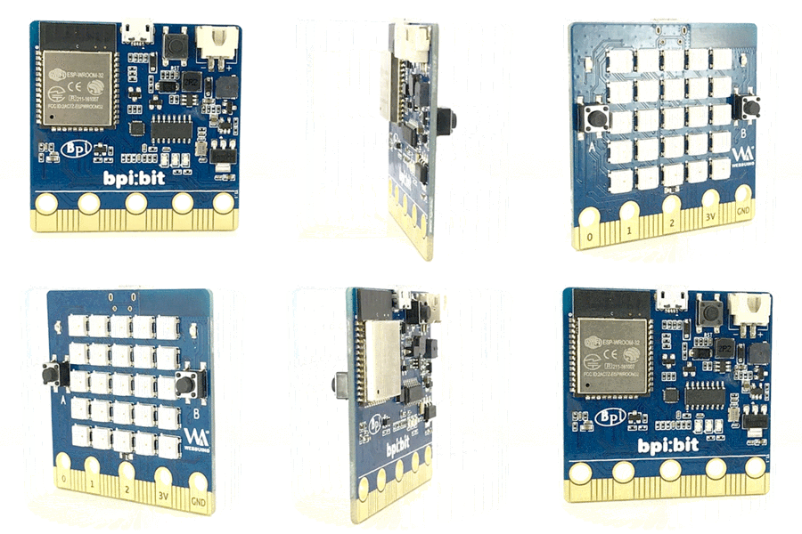
bpi-bit開箱文

拿到了bpi-bit(産品),打開盒子看到如下內容

 它的正面:

它的背面:
wiki上的圖片
簡介:
大小:5公分X5公分 ,重量:10至12公克,cpu:32位元Xtensa LX6雙核處理器,支援Webduino,Arduino,MicroPython以及Scratch X編程,內置20pin 針邊緣連接器,內置照明矩陣,25個可編程全彩LED,兩個光敏光傳感器,兩個可編程按鈕,一個NTC電阻,一個蜂鳴器和一個九軸傳感器(三軸加速三軸陀螺儀和三軸磁羅盤),I / O空間配置如下:
    全彩LED矩陣:GPIO4
    光敏傳感器:GPIO36(模擬A0,左上),GPIO39(模擬A3,右上)
    按鈕開關:GPIO35(Botton A),GPIO27(Botton B)
    溫度傳感器:GPIO34(模擬A6)
    蜂鳴器:GPIO25
    MPU-9250 9軸傳感器:GPIO0,GPIO21(SDA),GPIO22(SCL) 


它的wiki網址:http://wiki.banana-pi.org/BPI-Bit


2018年9月30日

bpi-bit韌體燒錄回weduino版本

如果bpi-bit的韌體版本跑掉了,想回出廠時的版本。依據文件做一次。
https://github.com/BPI-STEAM/BPI-BIT-WebDuino/wiki

參考網址:http://wiki.banana-pi.org/Webduino_firmware_programming

1.下載燒錄軟體
https://www.espressif.com/en/support/download/other-tools

點選esp32
2.解壓縮後,執行ESPFlashDownloadTool_v3.6.4.exe

 3.選擇4列,分别在第二欄填入四個位址x1000、0x8000、0xe000、0x10000,在第一欄選擇相對應檔案:

Filename Address
bootloader_dio_40m.bin 0x1000
partitions.bin 0x8000
boot_app0.bin 0xe000
bit_default.bin 0x10000

四個檔案下載位址:
https://github.com/BPI-STEAM/BPI-BIT-WebDuino
下載後解壓縮,在案在Bin資料夾中

燒錄後,如果出現X符號是沒按按鍵,要先按板子的A鍵不放再按後面的Reset鍵,然後再放掉Reset鍵,聽到蜂鳴器嗶嗶叫時,再放開A鍵。

快速還原方法:
在BPI-BIT-WebDuino-master資料夾中有AutoFlash資料夾,它可以快速還原韌體版本。
先執行AutoErase.exe,清除韌體,再執行AutoFlashWebduinoBin.exe,會自動寫入韌體,寫完後記得要按按鍵A後再按Rest,放掉Rest,聽到嗶嗶聲後放掉A鍵。

2018年9月28日

bpi-bit arduino ide設定

使用bpi bit讓arduino ide認識這塊板子做法:
作業系統ubuntu16.04 18.04
ubuntu使用apt-get  install的版本是2:1.0.5+dfsg2-4

按照
https://github.com/BPI-STEAM/BPI-BIT-Arduino-IDE/wiki#3-debian--ubuntu-os%E5%AE%89%E8%A3%85%E8%AF%B4%E6%98%8E

無法做出來。
我的解決方法(先sudo apt-get install arduino):
sudo usermod -a -G dialout $USER && \
sudo apt-get install git && \
wget https://bootstrap.pypa.io/get-pip.py && \
sudo python get-pip.py && \
sudo pip install pyserial 
 
下載新版的ardino ide
https://www.arduino.cc/en/Main/Software
 我用的是linux amd64 1.8.7版本
https://www.arduino.cc/download_handler.php?f=/arduino-1.8.7-linux64.tar.xz

下載完解壓縮

$tar Jxvf arduino-1.8.7-linux64.tar.xz
$sudo -s
#rm -rf /usr/share/arduino
#mv  arduino-1.8.7 /usr/share/arduino
#cd /usr/share/arduino-1.8.7/hardware/
#sudo mkdir  espressif
#cd espressif
#git clone https://github.com/espressif/arduino-esp32.git esp32
#cd esp32
#git submodule update --init --recursive
#cd tools
#python2 get.py
 
重新啟動arduino ide
在板子中才會有bpi-git可以選擇